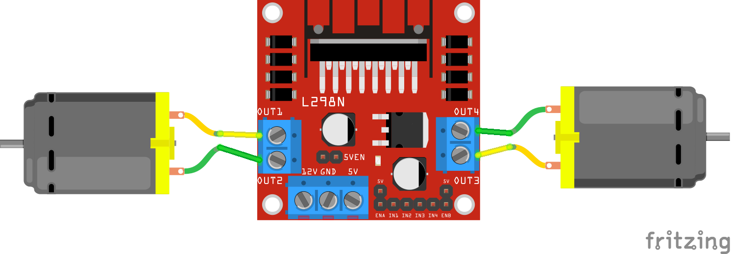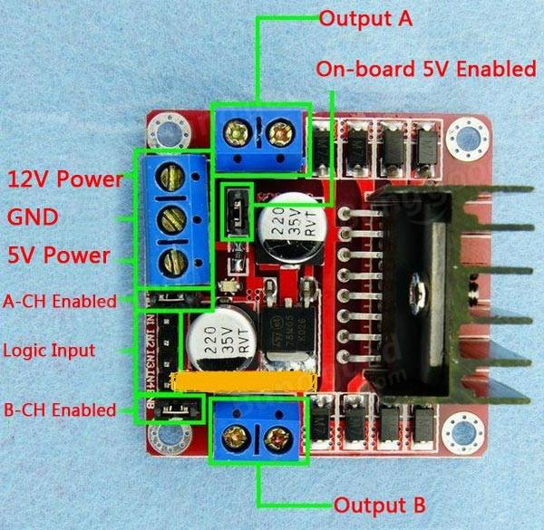

Logic Pins: Connect the Logic pins to any digital pins of Arduino. Keeping the jumper on these pins means that the these pins will be High. If you want to control the stepper motor with L298N, then keep the jumper on Enable A and Enable B. 5V pin will act as Output if the Vs will be less than 12V and 5V pin will act as Input if the Vs will be greater than 12V.Įnable Pins: Remove the jumpers on the Enable A and Enable B if you want to control the speed of DC motors and connect these to PWM pins of Arduino. If your supply voltage is greater than 12, then make sure to remove the 12V jumper. Power Pins: Give the supply voltage from 5 to 35V at the 12V pin and ground. If the supply voltage is greater than 12V, then remove this jumper and give the 5V supply to the 5V power pin so that the L298 Dual H Bridge IC can work properly. Motor A: This terminal block will give the output for the first motor.ġ2V Jumper: Keep this jumper in place if your supply voltage is less than 12V and the 5V power pin will give you the output of 5V.

It is inexpensive and perfect for robotic projects. It is recommended to always use the external voltage supply. The module can be powered from 5 to 35V from Arduino or external power supply. The module has an onboard regulator which helps in giving the output of 5V.

It can control motors which operates between 5 to 35V and up to 2A. The module will allow you to control the speed and direction of two DC motors. This module uses the PWM method to control the speed of DC motors. The L298N module has a very famous L298 Motor driver IC which is the main part of this module.


 0 kommentar(er)
